 The Raspberry Pi is quite popular among hobbyists and educators since its launch in 2011. The Raspberry Pi is a credit-card-sized single-board computer with a Broadcom BCM 2835 SoC, 256MB to 512MB of RAM, USB ports, GPIO pins, Ethernet, HDMI completely, digital camera header and an SD card slot. The essential appealing aspects of the Raspberry Pi tend to be its low-cost of $35 and enormous individual community following.
The Pi has actually a number of pre-built pictures for assorted programs, including the Debian-based Raspbian, XBMC-based (now known as Kodi) RASPBMC, OpenELEC-based Plex Player, Ubuntu Core, RISC OS and more. The NOOBS (New Out Of the container Setup) picture gift suggestions a user-friendly menu to choose and put in some of the a few distributions and afterwards boot into any of the installed OSes. The Raspbian picture comes with the Wolfram language within the setup.
Since its initial launch in February 2011, the Raspberry Pi has been modified four times, everytime getting updates but keeping the constant price of $35. The modern launch of the Pi (the Raspberry Pi 2) boasts a 900MHz quad core cortex A7 and 1GB of RAM. More over, Microsoft announced Windows 10 when it comes to Raspberry Pi 2 through its IoT developer program for totally free. This, as well as its functional features, has actually caused fans just like me to update on Raspberry Pi 2. With a few brand new Raspberry Pi 2 panels at hand, I set out to discover some of good use ways to employ my older Pi panels.
In this essay, We fleetingly explain the requirements associated with project that I outlined, and I also give an explanation for various tools I decided to utilize to construct it. When I cover the hardware We chose and method to assemble the parts to appreciate the system. Upcoming, we continue starting the growth environment on the Raspbian picture, and I walk through the rule and bring every little thing together to create the entire system. Finally, we conclude with feasible improvements and cheats that will extend the effectiveness of a Pi home automation system.
The web of Things
A continuing trend in embedded devices should have got all embedded devices attached to the Internet. The net was created as a fail-safe network that may endure the destruction of several nodes. The Internet of Things (IoT) leverages equivalent redundancy. With all the relocate to migrate to IPv6, the ip space would be large enough for a couple of trillion products to stay linked. A connected device in addition makes it very convenient to control it from anywhere, receive inputs from numerous sensors and respond to activities. A multitude of IoT-connected devices in property has the potential to do something as an income entity that exhibits response to stimuli.
Raspberry Pi Residence Automation
Encouraged because of the notion of having a property which includes a life of its very own, I settled on a home automation project to regulate the lights in my living room. The purpose of my task was to be able to time the lights in my living room and control all of them from another location on the internet using a Web browser. I also wished to expose an API that may be used to get a handle on these devices off their devices programatically.
The interesting element of this project isn't the hardware, that will be fairly easy and easy to make, nevertheless the UI. The UI that I had in your mind would help multiple users logged into the exact same Pi server. The UI condition needed to maintain the actual condition associated with system instantly indicating which lights actually were on whenever several users run the device simultaneously. Besides this, the lights may toggle on or down whenever brought about by the timekeeper. A UI operating on a device, such as a phone or a tablet, is subject to arbitrary link falls. The UI is anticipated to address this and make an effort to reconnect toward Pi server.
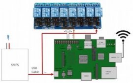
Wiring this can be time intensive but simple. Very first, wire the SMPS towards wall outlet by cutting-off an extension cable within plug end. Remove the wires and screw them to the screw terminals of the SMPS. After that, wire the Raspberry Pi to the SMPS by cutting-off the sort A end of the USB cable and wiring it into the line finishes regarding the SMPS additionally the micro B end towards the RPi. Get out two strands of cables through the ribbon cable, and line the right terminals to GND and JDVcc. Eliminate the jumper that connects the JDVcc and Vcc. Maybe not removing this jumper will feed-back 5v to the 3.3v pins of Pi and harm it.
Given that all terminals are wired for power, link the IN1-IN8 outlines for the relay component towards the proper GPIO pins of this RPi making use of a lot more of the ribbon cable as shown in Figure 2. The rule I present the following is written when it comes to instance in which I wire IN1-IN8 to GPIO1-GPIO7. In the event you opt to wire all of them differently, it is important to change your signal consequently.


